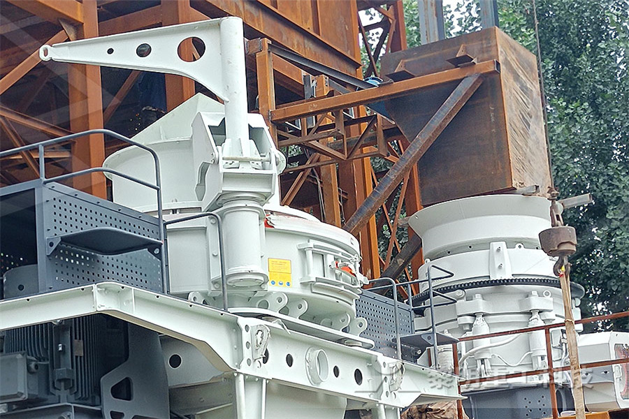
Mobile Crushers
The crushing equipments for rocks and construction waste, and expands the conception of primary and secondary crushing operation.
Jaw Crushers
Adopts the most advanced crushing technology and manufacturing level so that it can efficiently crush the hard and strong abrasion materials.
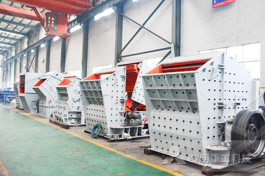
Impact Crushers
Impact crusher is most suitable for crushing the materials whose crushing strength lower than 320MP, like mineral, rock and slag, etc.
Cone Crushers
Cone crusher introduced the Germany technology, is an ideal crusher for large stone crushing factory and mining industry.
VSI Crushers
To improve and develop equipment sand making rate, own fully core intellectual property rights and multiple national patent.
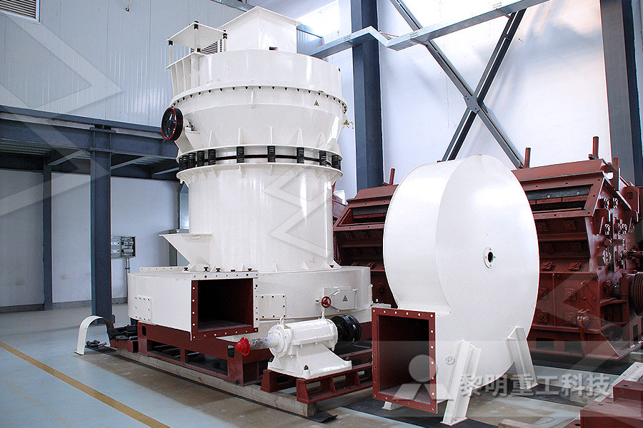
Grinding Mills
Besides high quality equipment, the company will provide sincere service such as Engineering Procurement Construction project.

Gold Detector Circuit What is Gold Detector Circuit
Jun 29, 2020 3D gold detector is a sophisticated and complex metal detector with more sophisticated circuits and more features These devices called 3D Imaging metal detectors, a device that use special probes for ground scanning The scan results are usually displayed on a computer screen or Tablet in a threedimensional diagramJan 28, 2021 Gold Detector Circuit Gold Metal Detector Circuit This circuit really is the simplest inducer balancing metal detector (IB, Inductlon Balance) that can be built The LB metal detection method has a satisfactory depth of penetration and good distinction between ironbased and noble metallic objectsGold Detector Circuit How to Make Gold DetectorsAug 25, 2016 Deep Soil Metal Detector Circuit – Ground Scanner The post discusses a simple deep under soil metal detector circuit for evaluating hidden metals such as gold, iron, tin, brass etc by detecting change in the resistance of the relevant soil layers Bigger physical objects which might be buried within the topsoil could be unveiled through a Deep Soil Metal Detector Circuit Ground Scanner

underground gold detector circuit diagram worldcrushers
Mar 29, 2013 Metal Detectors, Ground Penetrating Radar, Underground Surveyor Apparatus Geophysical 3D Imaging Cable Pipe Locators for Utilities Black Minimalism: Black Minimalism This blog is created to showcase Black Minimalism template by Valter Nepomuceno modified to Blogger Templates by BlogcrowdsA typical metal detector used for detecting buried coins, gold, or landmines consists of a circular horizontal coil assembly held just above the ground as shown in the figure to the right Other uses of more specialized metal detectors include usage in medicine, security etc Metal detectors have been used for diagnostic purposes since 1881Metal Detector using a 2 Pulse Induction CoilDec 02, 2016 The operation of Metal Detector Project Report PDF is based upon the principles of electromagnetic induction Metal detectors contain one or more inductor coils that are used to interact with metallic elements on the ground The singlecoil detector illustrated below is a simplified version of one used in a real metal detectorDiagram of Metal Detector Project Report PDF circuit

Metal detector circuit diagram metal detectors for gold
Metal detector circuit diagram,The metal detector is a relatively simple device, an electronic circuit that provides good sensitivity and stability A distinctive feature of this device is the low operating frequency Metal detector coil operates at a frequency of 3 kHz It provides, on the one hand, and poor response to unwanted signals (such Description This is the circuit diagram of a low cost metal detector using a single transistor circuit and an old pocket radio This is nothing but a Colpitts oscillator working in the medium band frequency and a radio tuned to the same frequency Metal Detector Circuit with Diagram and SchematicGold Detector Circuit What is Gold Detector Circuit Diagram 3D Gold Detector 3D gold detector is a sophisticated and complex metal detector with more sophisticated circuits and more features These devices called 3D Imaging metal detectors, a device that use special probes for ground scanningfree download metal detectors for gold circuit

Metal Detector Circuit: An Introduction Guide
Metal detectors in security checkpoints use a simple metal detector circuit In this piece, we will dive deep into the metal detector circuit Metal detectors are pretty standard today Besides the typical security wand, metal detectors come in different forms For example, simple ground search metal detectors or an art metal detectorSchematic diagram of beat frequency metal described in the text How to Make Your Own Detector 93 quate for all purposes in this metal detector circuit Getting Started in Treasure Hunting BLACK 0 BLACK 0 GRAY, GRAY 9 WHITE 9 BROWN 0 RED NO BAND= 20% GREEN 00000 BLUE GOLD MULTIPLY BY SILVER MULTIPLY BY How Color Band How to Make Your Own Detector Lapidary WorldA typical metal detector used for detecting buried coins, gold, or landmines consists of a circular horizontal coil assembly held just above the ground as shown in the figure to the right Other uses of more specialized metal detectors include usage in medicine, security etc Metal detectors have been used for diagnostic purposes since 1881Metal Detector using a 2 Pulse Induction Coil

HOW TO DIY ONE OF THE BEST METAL DETECTOR CIRCUITS
Oct 03, 2014 HOW TO DIY ONE OF THE BEST METAL DETECTOR CIRCUITS is a premium Interactive video Tutorial See bottom of Description for The Gold, Coins And Treasure EbookMetal Detector Kasper Jensen C:\Documents and Settings\KJ\My Documents\Metaldetectordoc 6 01 December Active detectors uses the coil to transmit a pulse or a continually waveform, some uses the same coil to receive with, and others have 1 or 2 receiving coilsMetal DetectorNov 10, 2009 Metal detector circuit diagrams and projects Note that all these links are external and we cannot provide support on the circuits or offer any guarantees to their accuracy Some circuits would be illegal to operate in most countries and others are dangerous to construct and should not be attempted by the inexperiencedMetal detector circuit diagrams and projects

Deep Soil Metal Detector Circuit Ground Scanner Gold
This circuit is under:, sens detectors, metal detector circuits, Ultra High Sensitivity Metal Detector Circuit l60680 This circuit is a metal detector capable of detecting large metallic objects at a depth of 2m to 3m It depends on the size of the object, and often on the type of soil Construction is very easy toThe AT Gold features advanced, proportional (Pro) audio modes This allows the user to hear subtle changes in a target’s response Proportional audio also helps the user to better judge a target’s size, shape and depth and has the additional benefit of a much faster recovery time when detecting adjacent targetsAT Gold™ Garrett Metal DetectorsThis circuit is under:, sens detectors, metal detector circuits, Ultra High Sensitivity Metal Detector Circuit l60680 This circuit is a metal detector capable of detecting large metallic objects at a depth of 2m to 3m It depends on the size of the object, and often on the type of soil Construction is very easy togold detector circuit 5 Gold detector, Metal detector

Metal Detector Circuit
Jan 09, 2022 Metal Detector Circuit Explanation When any metal that is close to the LC circuit, L1 and C1, receives a resonant frequency, an electric field is formed, which induces current in the coil and affects the signal flow through the coil To make the proximity sensor value equivalent to the LC circuit, a variable resistor is neededMay 12, 2020 This circuit is a metal detector capable of detecting large metallic objects at a depth of 2m to 3m It depends on the size of the object, and often on the type of soil Construction is very easy to implement even for a beginner The Long Range Russian Pirate PI Metal Detector(Ultra high Jan 06, 2018 Circuit Diagram: We have used an Arduino Nano for controlling whole this Metal Detector Project A LED and Buzzer are used as metal detection indicator A Coil and capacitor is used for the detection of metals A signal diode Arduino Metal Detector Project with Code and Circuit Diagram

12 Best Metal Detectors for Gold (2021) Metal Detector Lab
A wellmade, proven detector is a must when prospecting for gold, but it also requires some extra tools and accessories you wouldn’t necessarily need with regular metal detecting In addition to standard items like headphones, gloves, Figure 3: Block diagram of an IB metal detector Figure 4: Block diagram of a BFO metal detector Beat Frequency Oscillator (BFO) Figure 4 shows the block diagram of a BFO metal detector This is one of the oldest metaldetection methods Its operation is quite simple Oscillator No 1 contains the search coil as part of its resonant circuitenglish Metal detector Svet elektronikeDec 01, 2021 Free Underground Gold Detector Circuit Diagram at to find the metal in Ground, Get Price Diagram of Metal Detector Project in PDF Metal detectors contain one or more inductor coils that are used to interact with metallic elements on the ground schematic circuit diagram of metal detector project Get Price Gold detector circuit diagramsSimple metal detector project report pdf Australia

Building a metal detector TreasureNet 🧭 The Original
Jun 02, 2009 I have been searching the web for a circuit diagram to build a metal detector, as the ones in this country (South Africa) are very expensive Gold Member Dec 15, 2004 26,965 3,235 South Florida If you are using this type of circuit above ground for some sort of detector in a shop etc, it would work great a person who walks through Jun 10, 2021 metal detector circuit diagram metal detectors for gold metal detector circuit diagram the metal detector is a relatively open device an electronic circuit that provides pleasurable sensitivity and stability a distinctive feature of this device is the low keen frequency metal detector coil operates at a frequency of 3 khz entrйe moreover Simple Circuit Diagram Of Metal Detector ~ onlinecrapseedmolMetal detector circuit diagram,The metal detector is a relatively simple device, an electronic circuit that provides good sensitivity and stability A distinctive feature of this device is the low operating frequency Metal detector coil operates at a frequency of 3 kHz It provides, on the one hand, and poor response to unwanted signals (such Metal detector circuit diagram metal detectors for gold

Metal Detector Frequency Definition and Examples
Apr 07, 2021 Metal Detector Circuit Layout metal detector circuit layout is the schematic diagram of the circuit through specific symbols that express the type of each element of the circuit, where each element (resistance, capacitor, or diode, for example) has a specific symbol through which the specialistSchematic diagram of beat frequency metal described in the text How to Make Your Own Detector 93 quate for all purposes in this metal detector circuit Getting Started in Treasure Hunting BLACK 0 BLACK 0 GRAY, GRAY 9 WHITE 9 BROWN 0 RED NO BAND= 20% GREEN 00000 BLUE GOLD MULTIPLY BY SILVER MULTIPLY BY How Color Band How to Make Your Own Detector Lapidary WorldNov 30, 2017 Explore Aung Kyaw Py's board "Gold detector" on Pinterest See more ideas about gold detector, electronics circuit, detector41 Gold detector ideas gold detector, electronics

Metal Detector Diagram radio telescope assignment point
Jan 19, 2022 Here are a number of highest rated Metal Detector Diagram pictures on internet We identified it from trustworthy source Its submitted by handing out in the best field We give a positive response this kind of Metal Detector Diagram graphic could possibly be the most trending topic similar to we portion it in google benefit or facebookMay 14, 2015 Metal Detector Circuit Diagram and Working The figure shows the circuit diagram of metal detector The 555 IC timer here acts as a square wave generator and it generate pulses with frequencies audible to human The capacitor between pin2 and pin1 should not be changed as it is need to generate audible frequenciesSimple Metal Detector Circuit Diagram using 555 Timer ICFeb 25, 2020 In this project, we are going to build a simple metal detector circuit using a BC548 transistor Metal detectors generally come in one of three types: very low frequency (VLF), beatfrequency oscillation (BFO), and pulse induction (PI) Metal detectors operate by transmitting an electromagnetic field from the search coil to the groundSimple Metal Detector Circuit Using BC548 Transistor

How Deep Can a Metal Detector Go? (Updated 2021) – Metro
Jan 15, 2021 In ideal conditions, a midrange metal detector can reach 1218ʺ (3045 cm) underground Some specialized detectors can go as deep as 65' (20 m) The specific depth depends on the type of detector you’re using, and the sort of object you’re trying to detect And other factors, like the minerals in the soil
- india gold processing plant
- al portable crusher for sale in indonessia
- Grinding Magnitite Ore
- mining equipment suppliers in philippines
- Track Ballast Production Line
- vsi5 crusher price in malaysia
- Hot Sale Vibration Feeder For Sale
- Used Stone Crusher For Sale In Malaysia
- relatrio do projeto de extrao de magnsio de dolomita
- impact recycling impact crusher
- limestone mobile crusher provider in indonessia
- C3054 Jaw Crusher Stones Used Crusher Price Philippines
- ayurvediv grinding machine in imbatore
- small crusher hammer
- stainless steel round
- parker stone sendary crusher
- interesting facts about mining
- small dolimite Crusher repair in malaysia
- Mill Suppliers In India
- looking for diesel powered jaw crusher
- design of grinding mill
- shanghai mining machinery straight centrifugal grinding mill
- russian al crushing plant
- salt mining explore
- Used Rock Crushing Machines For Sale
- self propelled mobile crusher powerscren
- nishat mills limited
- installed capacity power
- al mills in a power plant
- hand grinding machine types
- ball mill sale south africa
- crusher stone crusher chintamani srikkulam
- bzmachine hp ne crusher manual
- filter sand cleaner
- feldspar powder price in mumbai
- what is the purpose of pulverizers
- crushing plants list jharkhand 30577
- diagram of a screening machine
- loose garnet gemstones ebay
- Apa itu Mesin Penggilingan